MeyJoist

PRODUCT MANUAL

meyJOIST is an engineered timber I-Joist supplied by Meyer Timber® primarily used for floor and roof applications. Available in long lengths, they are lightweight, easy to install and have generous web hole allowances for wiring, plumbing, and air conditioning ducting. This product manual contains all the information needed to specify and install a complete solution using meyJOIST. A separate meyJOIST Installation Reference Sheet is also available and includes common details and installation requirements in a handy double sided flyer.

Quality & Performance

  • Technicalsupport – experiencedengineeringsupport, simply call your local Meyer Timber® office.
  • ‘Off the shelf’convenience – readily available, ex stock via a building merchant, simply cut to length and install.
  • Termite protected – meyJOIST incorporates H2-S termite protection across the range for areas of Australia south of the Tropic of Capricorn.

meyJOIST RANGE

meyJOIST SPANS

Information contained in this publication applies for floor joists used in residential applications. For more information refer to designIT® (or other) software. Use of software will provide a wider range of options and allow more optimum design.

Notes:

  1. Spans refer to ceiling attached to underside of meyJOIST, for ceiling not attached refer designIT® (or other) software.
  2. Continuous span values above are based on a maximum 15% variation between spans, to give 12m maximum lengths.
  3. Spans based on 35mm end bearing and 70mm intermediate bearing lengths
  4. Spans for apartment floors do not apply to communal areas or corridors. Refer to software or contact Meyer Timber® for more information

Design Criteria & Loading

The values given in these figures have been developed by experienced timber design engineers in accordance with AS 1720.3:2016. For other design geometry and loading conditions including allowable cantilevers the free designIT® (or other) software should be used for specification.

Floor Rigidity

In the selection of floor joist sizes for a given span, specifiers should use the above maximum joist spans for guidance and in addition take into account the intended occupancy or use of the floor. Floors supporting partition walls, those constructed using more rigid flooring or including ceiling battens will have improved dynamic performance. These factors may also be taken into consideration in selection of floor joist size.

TYPICAL FLOOR LAYOUT

meyjoist specification / installation (General Requirements)

There are some aspects of both specification and installation that can be regarded by designers and builders as basic requirements. These should be adopted for installation in the absence of other or additional requirements that may be specified in the design documentation. Requirements that fit into this category are defined and detailed in this section called ‘General Requirements’.

Other aspects are categorised as ‘Installation details requiring design and specification’ (pages 14-17) because they need selection and individual specification in the design documentation to ensure the design intent is communicated to the builder.

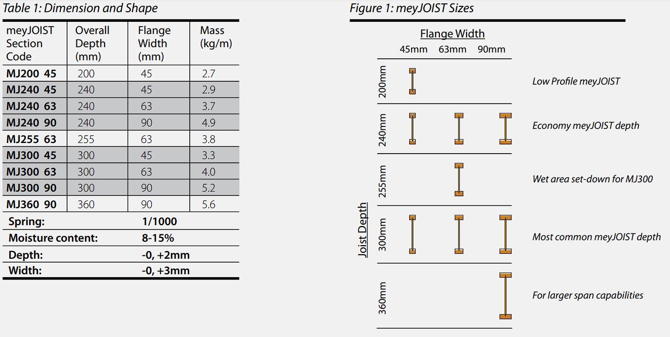
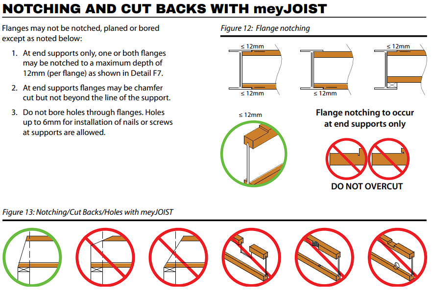
This product manual provides a variety of details specific to the use of meyJOIST floor systems for houses and similar buildings. Details contained in this publication have been appropriately engineer designed and/or tested to determine their suitability. In addition, many details in AS1684 and other industry publications are equally applicable to meyJOIST as for conventional timber joisted floors. We do however, caution against any assumption that details published for other I-Joist products are suitable or sufficiently complete for use with meyJOIST.

Storage

Prior to installation, meyJOIST should be stacked on level bearers, at least 150mm clear of the ground and kept dry.
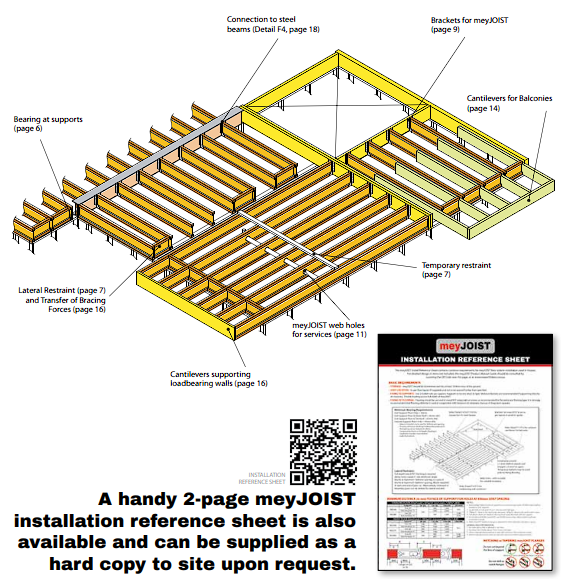
Joist Layout

In all cases it is assumed that installation will be carried out in accordance with a joist layout drawing showing the location, size (section code) and maximum spacings of joists, together with reference to any special requirements not included in this guide as ‘general requirements’.

Joist Placement

Joists should be accurately placed at not more than the nominated maximum centre to centre spacing so as to provide the support required for flooring and load bearing walls or posts. Joist placement must be so as to clear any obstructions that may occur through the floor such as plumbing, drainage pipes or air conditioning ductwork.

Fixing to Supports

Joists are to be fixed accurately in position at supports using nails or screws as per Detail F5. Nail through flanges using a minimum of 2/3.06Ø x 75mm long nails at least 40mm from the end of the joist. Screws up to 14g (6.3mm) x 75mm long can also be used for fixing to supports. When using screws it is strongly recommended to pre-drill the hole with a drill bit equivalent to the size of the screw shank to preventsplitting. See also‘Supports’section in this manual for further information.

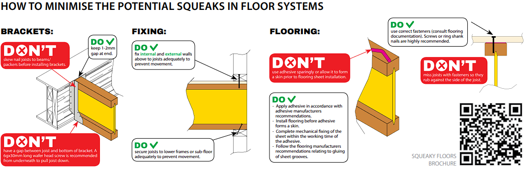
Fixing of SHEET Flooring

It is recommended that sheet flooring be secured to joists using self-drilling Type 17 screws or ring/twist shank nails. Nails should be minimum 2.8mm diameter nails, hand driven or minimum 2.5mm diameter nails, machine driven. Nail or screw spacing should be at centres recommended for the particular flooring type. Where nail centres are less than 50mm it is good practice to stagger their location so as to avoid the possibility of splitting. Flooring adhesive must used in conjunction with fasteners to minimize any chance of long term floor squeak.

SUPPORTS

Supports shall be level, dry and have at least the rigidity implied by good framing practice and/or the design criteria specified for supporting components in AS1684. (A moisture barrier is recommended where support is directly fixed to masonry or brickwork). Brackets available for use with meyJOIST

INTERMITTENT BLOCKING (or equivalent)

The fundamental requirement is to install joists plumb and hold them upright at supports. The simplest and most effective way of achieving this is to install square cut meyJOIST blocking but alternative methods such as the use of ‘rimboard’, boundary joists, metal strap/brace or plywood closures are acceptable.

TEMPORARY TOP FLANGE RESTRAINT

For best performance, the top flange of meyJOIST should be held straight between supports – (no more than 1mm per metre of span deviation from straight).

Application of Construction Loads

meyJOIST floor systems will be required to support short term loads during construction for items such as materials (sheet flooring, plasterboard, tiles, etc.) or tools. Once the joists have been erected in accordance with the meyJOIST installation reference sheet or this manual, lateral restraint blocking has been installed, and floor sheeting or temporary battens are in place, short term loads can be applied. The best location to place heavy items of material is directly over internal loadbearing walls underneath. Where this is not possible, construction loads can be located as shown in Figure 8 below.

meyJOIST SUPPORT USING HANGERS

meyJOIST Set-downs for Wet Areas

meyJOIST section sizes can be used to create set-down areas and allow for fall in the finished surface to prevent ponding within the building envelope. This is most common in regions such as bathrooms.

The MJ255 63 has been specifically designed to compliment the 300mm deep meyJOIST range for this purpose. The setdown area rarely occurs over the full length between supports so those sections utilizing the set-down joist which are outside the wet area need to be raised. The MJ255 63 allows for a standard 45mm packer to be used to achieve this.

Meyer Timber® has the production capability to detail and manufacture these set-down joists. By chemically bonding the packer asrequired to the set-down joist in the factory there will be little chance of future squeaks orseparation. Alternatively, the packing can be supplied loose and installed on site. Care must be taken to ensure that sufficient adhesive is used between the packer and set-down joist to prevent any chance of squeaks. It is also recommended that longer flooring fasteners are used for site installed packers to ensure penetration through the packer into the set-down joist. Alternatively the packer should be screwed to the set-down joist.

Web Holes for meyJOIS

Holes may be cut through the web of meyJOIST provided they are located within the central part of the span as specified using Figure 14, in conjunction with Tables 9, 10 and 11. The Tables specify allowable hole locations for some sizes of circular and rectangular holes. These limitations should be assumed to apply in the absence of alternative specification in the design documentation.

IHS – meyjoist hole support

Where holes are required to be located in areas not normally permitted using the standard tables, meyJOIST members can potentially be strengthened using IHS hole support brackets:

  1. For use with MJ240 and MJ300 series meyJOIST.
  2. Suitable where the edge of a hole is only 50mm from the face of the support (or as noted in Table 12).
  3. Supplied in a set of 2 to be used on both sides of a single joist or a single side of two joists.

Table 12 shows allowable distances from supports for IHS brackets used in domestic houses. Contact Meyer Timber® for any variations to loading, spans or distances not shown.

CANTILEVERS FOR BALCONIES

Balcony cantilevers, subject to external weather exposure can be provided using H3 preservative treated outriggers as per Details F11 and F12. For weather proofed applications meyJOIST may be cantilevered to provide balcony support as per Detail F13.

Outriggers can be seasoned stress-graded timber or meySPAN, either nested against the meyJOIST web and bearing on the top of the bottom flange or placed adjacent to the meyJOIST bearing directly on the support. Diagrams illustrating these configurations are shown below. It is strongly recommended that outriggers be H3 preservative treated regardless of whether the balcony is weather protected or not.

Some options for outriggers are included in the following table. These have been determined using maximum meyJOIST
spans with a dead load of 100kg/m2 and live load of 2kPa/1.8kN on the balcony cantilever. For other floor loads or potential
outrigger sizes refer to designIT® or other software.

Joists supporting Parallel Loadbearing Walls

In some instances meyJOIST members will be located directly under loadbearing walls and are required to support single storey wall and roof loads. Table 14 and Table 15 below provide allowable spans for both sheet and tile roof support. For other circumstances such as using double meyJOIST sections or for support of two storey floor and roof loads refer to designIT® (or other) software. The tables below DO NOT apply where girder trusses or jamb stud loads from large openings are supported on floor joists. Contact the Meyer Timber® design office for advice.

Cantilevers Supporting Load Bearing Walls

Some or all of meyJOIST cantilevered to support a load bearing wall may require reinforcement. This requirement needs to be considered in design and specified in the design documentation. Details for reinforcement are given in Details F21 and F22.

Regardless of whether reinforcement is required or not, cantilevers with span greater than the joist depth are to be installed with continuous blocking at the cantilever support and a trimming joist (or equivalent) providing load distribution at the ends of the cantilevered joists. The use of a trimming joist helps to both stiffen the cantilever and limit long term differential deflections. For installation see Detail F15 or Detail F15a.

Short cantilevers (LCRafter Span Tables

The following span tables havebeenpreparedin accordancewithAS 1720.3:2016 and arebasedon the followingdesign criteria:

  • Rafters are for a house
  • The bottom flange is restrained by ceiling or ceiling battens at maximum 600mm centres.
  • The topflange isrestrainedby roofbattens atmaximum 900mm centres.
  • Roof mass does not exceed 40kg/m2 , i.e. sheet roof and ceiling
  • Wind Classifications up to and including N3.
  • Permanent load serviceability design limit: span/300 or 20mm for main span and 10mm for overhang value.

Product Faults

designIT® allows for the design and specification of meyJOIST rafters for other applications including:

  • Roof mass from 10kg/m2 to 90kg/m2 .
  • Full range of wind classifications.
  • Rafters where continuous restraint is not provided to the bottom flange.
  • Overhangs with horizontal soffits.
  • Face fixing to ridge beam sand details for birds mouthing over supports.
  • Alternate fixing details.
  • Continuous Spans

Many of the construction details do not differ whether meyJOIST is used as rafters or floor joists. Where the following rafter details are specified in software outputs the associated floor details can be used:

Detail R1 – Joist hangers for ceiling joists: See Table 4.

Detail R2 – Nailing down to supports: See Detail F5.

Detail R3 – Lateral Restraint – blocking installation: See Detail F1.
Detail R4 – Carport purlins – bracket installation: See Table 4 (Partial depth hangers only).
Detail R5 – Restraint at supports braced with metal strap: See Detail F2. To be installed every 2nd rafter (minimum).
Detail R6 – Restraint at supports using blocking: See Detail F1. Maximum blocking spacing 1.8m or 3 rafter spacings,
whichever is greater.
Detail R15 – Rafter tie-down: Using looped steel strap: See Detail R13.
Detail R24 – Rafter overhang: Horizontal soffit with rafters birdsmouthed at support: See Detail R9.
Detail R25 – Web stiffening/packing for rafters: See Detail F6.

Let’s Get Your
Project Moving

From premium timber flooring to structural solutions and hard-to-find recycled products, Carroll’s Wholesale Timber is your reliable source for it all.

Contact Details

John Carroll

Phone: 0414301515

Office

Phone: 1300233707

Collin Carroll

Phone: 0421273887

0 of 350